Showing posts with label MPLAB-X. Show all posts

Saturday, July 28, 2018

dsPIC33CH128MP505

Why?


So back in June, AB Pearce mentioned on the piclist that Microchip had introduced some dual-core PICs.  Apparently they had been out for some time, and talked about in the Microchip forums, but I hadn't been aware.

So I did a little exploration, they look reasonable, checked out the pricing on Newark and Digikey, and ordered a couple dsPIC33CH128MP505 and a dsPIC33CH128MP506. I didn't really have the time to play with them, but I figured might as well have them on hand for whenever I did find the time.


Of course, the bright, shiny things kept calling, so more important things got pushed out of the way to play with the dual-core dsPIC.

Description


For my testing I selected the dsPIC33CH128MP505; with only a few LEDs and maybe later something else, there seemed to be no reason for the 64 pin dsPIC33CH128MP506.

The dsPIC33CH128MP505 is a 48 pin part, I ordered it in TQFP because I had some TQFP adapters that would work and there were no DIP parts.  The master core is more or less as expected, 128K of flash program memory, 80 MIPS so a tad faster than my favorite dsPIC33EV.  The slave core has 24K of program RAM, and at 100 MIPS is slightly faster still.  Obviously, since the slave program memory is RAM, the slave program has to be loaded by the master, so it needs to be stored in the master flash.

Each core has its own set of peripherals, slightly different from each other.  All input pins are accessible to both cores, but outputs must be assigned to one core or the other. Like other dsPIC33's, the peripheral complement is huge.

There is the typical set of PRI, FRC, LPRC oscillators, with or without PLL, shared by both cores. Each core can select the oscillator and has its own PLL chain. The PLL chain is slightly different from the dsPIC33E, but conceptually similar.

One interesting thing is that the datasheet indicated that the outputs can drive LEDs without the need for current limiting resistors. On my test board I used them anyway, because that's what I do.

Test board


In order to do something, I built up a simple test board. I generally power my PIC projects with a cell phone charger which provides 5 volts, so my board needed a 3.3 volt supply. A connector for programming, some assorted caps and resistors, and a few LEDs were all that I needed to hack together something to play on.


I am generally a little cavalier about bypass caps on prototyping boards, but in this case, the processor wouldn't run until I sprinkled a few around in obvious places. That is actually the first time I ran into that.


Programming the master


Getting the master to blink an LED was no big deal. The only surprise was that there are an incredible number of configuration bits. The bits are shared between master and slave. Many apply to both, but there are some that are specific to the core. All are provided in the master core's program.

Besides the fuses you might expect, every pin has a fuse to assign it to either the master or slave. There is a data direction fuse for each of the mailbox registers. There are also bits to enable each of the mailbox protocol blocks and to assign them to a mailbox register. Each of the four sets of alternate registers can be assigned to an interrupt level. The master and slave can each have independent ICD communications pins.  All in all, an intimidating set of configuration fuses.

Once you get past the shock of the configuration bits, programming the master is unexciting, as long as you are only programming the master.


I did set up the master and slave program projects as subdirectories of a sort of master directory, and placed both projects in the same git repository. Although small repos are generally better, in this case the master and slave are closely linked, so it seemed to make sense.


Programming the slave


Getting the slave to run is quite another can of worms. There is, of course, the datasheet, the Family Reference Manual, and an application note, AN2721, which has some associated sample code.  Even with this documentation, there are a number of secrets that aren't obvious.

The documentation seems to indicate that the slave program must have the same name as the master's, followed by S1. This doesn't seem to be a requirement, although I haven't tested that supposition. What you do need to do, though, is select a processor name followed by S1 when creating the slave project.  So the project for dsPIC33CH128MP505 is the master program, and the slave program uses dsPIC33CH128MP505S1 as the processor type.


Since xc.h takes care of the processor, it isn't 100% obvious that there are also two header files, p33CH128MP205.h and p33CH128MP205S1.h, which becomes important because often the headers need to be explored to understand what the documentation means, or more often, to fill in the blanks.

Everything is slave 1 this and slave 1 that, so it appears Microchip is leaving the door open for parts with more than one slave core. Since the slave program has to be stored in the master's flash, it would seem that multiple slave versions are going to need an awful lot of flash.

The slave core's program is loaded with a call to _program_slave(), obvious enough, and the slave started with a call to _start_slave(). Also seems fairly obvious. However, the _program_slave() call takes three arguments. The first is the number of the slave. The second is whether the program is to be "verified", whatever that means. The final is the address of the slave program.


And that's where it gets interesting. When creating the master project, a new folder, "Slaves", is created. The slave project must be added to this folder in master. So far, makes sense. If the slave program is going to be stored in the master flash, the master needs to know that it needs to be linked in.


The address in the master flash can be specified in the slave project properties in the Slaves folder. But, referencing that address in the _program_slave call doesn't work!


The examples from Microchip all use the slave project name in the _program_slave() call. However, simply stuffing that in doesn't work. The examples always included the slave's include file in the master's mainline, which I assumed somehow declared the symbol. But I could find no combination of attributes that worked. Worse, in the example code, I could never find that particular include file.

It turns out that referencing the slave's include file, even though it is in another project, does the trick. The include file can even be empty.  I suspect it might not even need to exist, although I haven't tried that yet. Also note that _program_slave() and _start_slave() are defined in libpic30.h.
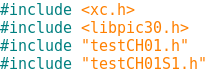

Once that was in place, I was able to flash an LED from the slave. But to understand that the master and slave were both working, I thought it would be helpful to start and stop the slave.  While libpic30.h defines a _start_slave() function, there is no function to stop the slave.

The slave is started by setting the SLVEN bit in the MSI1CON register. This register, like the EEPROM in the 8 bit parts, requires an unlock sequence. Since I may want to do this in the future, I wrote a stop_slave() function.


I did find it rather curious that the assembler played like a compiler a bit, and modified my code. Where I cleared the SLVEN bit (bit 15) in the MSI1CON register, the generated object code cleared bit 7 in the MSI1CONH register, apparently saving a little time.

I was now able to start and stop the slave as needed.  In theory, one could have multiple slave programs and switch between them under master control. In this case it would be important to be able to stop the slave. Lacking a stop_slave() function in libpic30 seems like a significant oversight.

Mailbox Communications

Now that I could program, start and stop the slave, the next step is communicating between the two. So on to sending data from the master to the slave. There are two ways to do this, through mailboxes or through a FIFO. I decided to try the mailbox first.

Slave Output

Being able to understand that I was successful in sending data from master to slave was going to take more than an LED as a way to let me know I was successful. Previously, I had built a PIC32 based Serial Graphics Terminal  for just this problem.  So I added a connector for this terminal and a litttle code to communicate.

Unfortunately, I had some hassle with this. I'm not sure whether I forgot some initialization or didn't have the baud rate quite right, but the objective was to try out the mailbox communications, not debug the terminal, so I fell back to my
Simple Terminal which only does text. Since this application is really dumb and has no cursor control, it is fairly slow, but adequate for this purpose.


Mailbox Communications


The 33CH provides 16 mailbox registers which are visible to both master and slave. They are unidirectional; each must be assigned as master to slave or slave to master.


There are up to eight protocol blocks. A protocol block is a sequential group of mailboxes going in one direction. The final mailbox in the group triggers the transfer. Again, more configuration bits to enable a group and assign the register.


You can see how we come up with over 100 configuration settings.

Once the configuration bits are set, the exchange is fairly easy.  The master enters the data into the mailbox registers, taking care to load the last register in the handshake block last. Writing the last mailbox sets the data ready bit for the slave.


Master then waits for the data ready bit to clear, indicating that the slave has retrieved the data.

On the slave side, it waits for the data ready bit, then reads the data. When the final mailbox is read, the data ready bit is automatically cleared.


Note that the registers have different names on the master and slave side.

Graphics Terminal Output


FIFO Communications

FIFO communications, if anythig, is even simpler than mailbox, assuming no handshaking anyway.

The master and slave each  have a control register for the FIFO,  MSI1FIFOCS for the master and SI1FIFOCS for the slave. The receiver sets a read FIFO enable bit, while the sender sets a write FIFO enable bit.  The sender then stores data into the FIFO which the receiver can retrieve.

As an example:


Summary


So the dual-core PIC is pretty manageable. There is still plenty to explore.

But I am thinking wouldn't it be nice to have the master run a DDS while the slave runs the keyer.  I may need to try that.

The code for this is in gitlab as always.

73 de WB8RCR

Monday, July 24, 2017

A GPS adjusted clock


We recently got a new cable box.  The new box has a clock that is a little smaller than the old one, and my wife has a hard time seeing it. We had an LCD clock with huge letters but there just isn't enough light in the place we want it.

So, NE06 GPS modules are getting pretty cheap. Why not get some huge seven segment LEDs and build up a clock based on a GPS?  Turns out large LED displays are fairly hard to come by, and pretty expensive. Plus, all that wiring to all those pins is a pain.

Then it hit me: I have some TFT displays, not huge, but plenty adequate for inch or inch and a half high digits.  If I used the TFT, I wouldn't even have to build the board; I could use my serial graphics terminal board.

First step was to see if I could make huge letters without too much hassle (the largest font I have is only about 3/8" high).  The first whack isn't too bad. It will work, although I might yet do some prettying up of the font.


So, on to the GPS.

I started with my serial terminal code, which may have added more complexity than I needed, but it works.  This code fills a circular buffer with serial interrupts from the GPS and the mainline has to process the contents of the buffer. This makes missing characters less likely but it does mean the mainline is futzing with trying to understand whether there are characters in the buffer and identify the start and end of the GPS data.

Parsing the GPS data is tedious, but not especially difficult.  With the PIC32MX150F128B there is plenty of memory, so I can be pretty aggressive with my code.  Most of the code is the TFT library so the stuff I'm working on is pretty small anyway.

At this point I can get the time and coordinates (which I don't need).  I am displaying all sorts of values which eventually won't be used.


Next up is to get the date, and go through the tedious business of determining whether it is daylight savings or standard time. The correction is trivial but knowing when to apply it is a pain.

Following that I'll get after the PIC's real time clock calendar.  Supposedly the PIC can maintain the time to within a third of a second per month.  I'm not convinced can actually accomplish that, but adjusting it from time to time through the GPS should keep the time always correct.

Since even in the basement with overcast skies I can still see 8 to 11 satellites that might be overkill.  If I have too much trouble with the RTCC I might just skip that, but the next priority is the daylight savings time thing.

The code is currently partial, and pretty rough, but as always I keep everything in git and the current code is in gitlab:
    https://gitlab.com/PIC32MX/gpsTime.X

The board hardware is at
  https://gitlab.com/PIC32MX/tft-board-pcb

And the TFT library code at
   https://gitlab.com/PIC32MX/TFT.X

They will be updated as time goes on.

170807:
OK, so some code cleanup, and slightly larger digits, but still significant work to do:


The digits are actually a tan color, but it doesn't show in the picture.

170824:
And yet another little tweak.  After seeing the clock it occurred to me it would be a nice addition to the shack, too, providing it showed UTC as well as local.

Sooo.....


 Time to get on to making cases, perhaps.

Saturday, January 14, 2017

Really ancient history

A long, long time ago, roughly around the time of the invention of the wheel, I did a series of lessons on 8-bit PICs. These lessons were very well received, downloaded thousands of times, and although aimed at hobbyists, many professionals also used them as an introduction to microcontrollers.

Craig Johnson made an experimenter's board to help with these lessons, which was originally kitted by the American QRP Club and later by Kanga U.S. Over the years this board underwent a couple of revisions, and is still available from Craig directly.

I have continued to get questions about these lessons, even though it is over a decade, and the target micro, the PIC16F84A, pretty long in the tooth.   Most of the more recent questions have to do with the development environment, which has changed pretty dramatically since MPLAB 6.

I finally broke down and decided to update a couple of the lessons, those that go into great detail about manipulating MPLAB.
Of course, I based them on MPLAB-X, rather than MPLAB 8.  MPLAB-X was pretty rough during the beta testing, but has evolved into quite a nice IDE. Reviewing these old MPLAB documents reminded me of just how much the environment has improved. I also updated the screenshots and some of the prose for Windows 10.  I don't use Windows much myself, but these days most people do, so it seemed to make sense.

The lessons are both available on gitlab in pdf; Lesson 3 which does some initial exploration of MPLAB-X which is available here, and Lesson 4 which explores the MPLAB-X simulator in some detail here.

 The only other lesson that is tempting is Lesson 11.  It goes into a lot of detail about manipulating a program called FPP, which is no longer available. The replacement, tho, hardly seems worth it.  On MPLAB-X with the PIC-EL III it reduces to "click this button".

So perhaps that will reduce the emails in the future.  In any event, it should make things easier for those who are finally getting around to doing Elmer 160.


Saturday, March 19, 2016

Getting started with MPLAB-X

 A long, long time ago I switched to MPLAB-X from MPLAB 8.  Since at the time MPLAB-X was in beta, the transition was not all that smooth.  Since then, MPLAB-X has gotten more stable, I've gotten accustomed to it, and the feature set has expanded.  Now it is way better than the old MPLAB ever hoped to be.

An even longer time ago I wrote a series of lessons on programming the PIC16F in assembler language using MPLAB 6 (yeah, that long ago).  Craig Johnson, AA0ZZ, produced a board to go with the lessons, and that board, and its descendants, continue to live on through a Yahoo group.

I never updated the course for the newer PICs or the newer IDE, but occasionally questions come up on that group which prompted me to make a series of screenshots using MPLAB-X.  I considered (for about a millisecond) updating the lesson on MPLAB but got over it.

But here I will provide a little prose for those wanting to get off the ground in MPLAB-X.  I should mention that this assumes you want to do 8-bit assembly programming, not because I think that is a good thing in this day and age, but more because I think that is the audience.  These days I am much more of a fan of the 16 and 32 bit parts in C.  The 8-bit C compilers (and they are legion) are all pretty weak  (see my SDCC post), and I am a fan of C.  But for the 8-bit parts, I still think assembler is the way to go.

When launching MPLAB-X, the opening screen is kind of busy.

Start page, first time

This shows the 'Start Page', a tab (lots of tabs in MPLAB-X) showing some Microchip marketing stuff (actually, some of it quite useful), but most importantly, your recent projects.  If you are launching MPLAB-X for the first time, of course there are no recent projects.

Recent Projects List

In the screen shot this is the first time MPLAB-X is opened, so there are no previous projects.

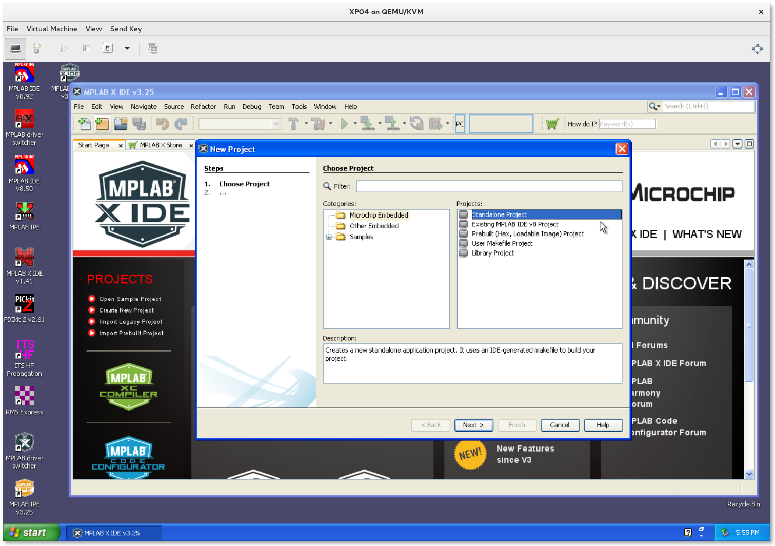
Clicking the new project icon (the yellow-ish folder icon on the left) launches the new project wizard.

New Project Wizard

The first panel of the wizard is a little confusing at first. What you want is 'Microchip Embedded' on the left and 'Standalone Project' on the right.  The other choices are useful, but not at first.

Clicking Next leads you to a panel to select the processor.


Processor Selection

You may choose a family and then a processor from the drop down menus, but there are a lot of PICs in each family.  it is easier to simply highlight the Device field and type in the name, or part of the name to narrow the search.

The next panel allows you to specify your programmer.


Programming Tool Selection

That is pretty simple business.  The next panel lets you select the toolchain.


Toolchain Selection

The default installation provides the Hi-Tech compiler and MPASM.  To do 16 or 32 bit work you will need to install additional compilers.  They will then show up here.  When you update compilers, previous versions will continue to be shown until you uninstall the older version.

Finally, you get to name your project.


Project Name

The first time, Microchip defaults to an MPLABXProjects folder.  This is a perfectly good place, but if you would prefer your projects somewhere else, click Browse and navigate to your favorite place.  The directory defaults to the last location you used, so there is no penalty for disagreeing with Microchip.

When you click Finish, your project will be created, however it will have no source files.

Creating new file

Right-clicking Source files on the left will bring up a context menu that allows you to specify whether you want to create a new file or add a file you have previously created.  Rolling over New will launch a sub-menu allowing you to specify the type of file you wish to create.

Additional File types

Should you choose Other, you get a dialog giving you additional choices.


New File Name

Clicking Next will allow you to finally give the new file a name.  MPLAB-X will provide the extension appropriate to the file.

If you are following the Elmer 160 lessons, the early lessons use absolute code, but MPASM defaults to relocatable code.  To specify absolute:

Project Properties Button
first click the Project Properties button alongside the Dashboard.  Then highlight mpasm (Global Options) and tick the Build in absolute mode check box.  Click Apply then OK.

mpasmx Options Selection

Double-clicking the file name in the left pane will open the file in the right pane.  You may now edit the file.  If the file has not been saved, its name in the tab will be bold.  For most files, the source code will be highlighted in color.  


Editing the code

When you think you are ready to build, clicking on the Build Main Project button (the hammer) will assemble and link your project.

Build Main Project Button

You will see all sorts of messages fly by in the lower right pane.  What is important is that at the end of those messages,  you see BUILD SUCCESSFUL in green.

Build Success

During the build there may be a lot of messages produced.  If you see the green BUILD SUCCESSFUL you can ignore them.  But if there was an error, you will get a red BUILD FAILED message.  In this case you need to scroll that window up and find the first message that isn't black.  Sometimes this can be quite a way up, but when something fails it can often cause other things to fail.  It is important to find the first message, because if you try to fix the later messages first, you may end up breaking more things.  Be sure to find the first message and fix that.  Then review the later messages and see whether they still make sense.

Build error

Once you have a successful build, you can program your target project by clicking the Make and Program Device button (with the green downward pointing arrow).

Make and Program Device Button

Normally this will go fairly quickly, but depending on what you have done (or not done) previously, it can take a while.  The first time you program a particular family, MPLAB has to download code into the programmer.  This can be pretty slow.  If you haven't changed device families, it will go quite quickly when you program the same device again.  Programming some PIC32 devices with a PICkit can also be quite slow.  If you are working with these devices you might consider an ICD instead which is significantly faster.  Ditto with very large programs.

Programming Success

Once again, a number of messages will go flashing by in the lower right pane.  When you see Programming/Verify complete your project will be ready to test on the target hardware.  And again, if you see red, there is a problem.

Programming Failure

I have an old YouTube showing this process.  In spite of all the steps it can be quite quick.  The video is for a dsPIC on a much older version of MPLAB, but the steps are all the same, even if the screens look a little different.

WARNING: There are lots and lots of tabs in MPLAB-X, and almost every tab can be dragged almost anywhere within the window.  If you happen to drag a tab off the window it will become un-docked and separate from the main window.  You can re-dock it from a menu on the small window.  Should it land on the window border, it will be hidden and marked with a tiny icon on that border.  It can be opened from that icon.

Right-click is your friend.

There are a lot of features in MPLAB-X.  Later posts will explain some of these features.


Friday, March 18, 2016

MPLAB Xpress

Recently Microchip introduced MPLAB Xpress.  This is basically MPLAB-X in your web browser.  It looks for all the world like MPLAB-X except you don't need to install anything on your PC.  Just point your browser to the IDE and have at it.

MPLAB Xpress in Internet Explorer

At the current time it looks as if it only supports 8-bit PICs.  Kind of a pity because, IMO, the 8 bit C compiler is trash.  The 16 and 32 bit compilers are ports of gcc, the benchmark for C compilers.  But still, if you like the 8-bit stuff, it is pretty neat.  You can do MPASM in MPLAB Xpress although getting started isn't real obvious.

If you want to use your PICkit online, you do need to install a bit of software.  There is a USB bridge to connect your PICkit to the online IDE.

If you don't have your PICkit connected, the hex file can be downloaded.   Otherwise, you can keep your entire project "in the cloud".  Actually, kinda handy if you want to do development on a tablet or across a number of devices.

To push this model, Microchip offered a free evaluation board.  It is supposed to be available on MicrochipDirect soon, but I couldn't find it today.  The target price was supposed to be quite low, too.


MPLAB Xpress Evaluation Board

This is a way cool little board.  It has a microUSB connector, and when you connect it to your PC it presents itself as a USB drive.  To program the PIC, simply drag the hex file to the USB drive.

The board has a PIC16F18855, a pot, a button, and a few LEDs.  All the pins are brought out to the edge of the board although not all the connectors are populated.  There are a number of demo programs available on the Xpress IDE.

The PIC16F18855 is a pretty impressive little part, even more impressive when you check the Digikey price.

The part includes:
  • 8K words of program memory
  • 1K bytes of SRAM (pretty fat for a 16F)
  • 256 bytes EEPROM
  • 24 channel A/D
  • A DAC
  • A CRC generator
  • 3 waveform generators
  • A numerically controlled oscillator
  • 4 configurable logic cells
  • A data signal modulator
  • Peripheral Pin Select (a huge win, IMO)
  • And of course timers, comparators, PWM, I2C, SPI all the normal stuff
The evaluation board contains the 28 pin PIC in a tiny (4x4mm) UQFN package.  Curiously, the PIC18LF25K50 used for programming is in a larger QFN (6x6mm) package.  The PIC is available in a 28 pin SPDIP and its bigger brother in a 40 pin PDIP if you want to move your development to a more hobbyist-friendly environment.

Digikey currently shows the SPDIP version for under two bucks, and the 40 pin PIC16F18875 for $2.04.  Pretty impressive for all those peripherals.

All in all, a pretty cool way for someone to get started in PIC development without installing anything.


Saturday, August 8, 2015

Club Project - Thermometer

Recently the local radio club needed something to spice things up, and the idea of a construction project based on a PIC seemed to be well received.  I came up with the idea of a PIC based thermometer, a little off the beaten path perhaps, but easily done.


An awful lot of PIC projects involve nothing more than an LCD and a sensor of some type.  Everyone has done some sort of test instrument; counters, capacitance meters, dip meters, signal generators, and on and on.  But a lot of the club members don't do a lot of building, and while a counter is kind of cool, it only appeals to the more technical members.

A thermometer, on the other hand, is something that everyone can get behind.  Perhaps you won't play with it for very long, but you will play with it.  You will hold the temperature sensor and watch it warm up, you might put it in the freezer, perhaps it will find a permanent home in the greenhouse.  But it is something everyone can at least play with, if only briefly.

I also wanted to try to inspire folks to pick up a soldering iron and perhaps grok a little code long after the build session.  A thermometer based on the Maxxim/Dallas DS1821 is dead simple, and as a totally digital solution requires no calibration, and the adventuresome could easily stick the sensor on the end of a long wire to put it in the garage, or in the garden, or wherever.

For similar reasons I chose the PIC24FV16KM202.  It has a lot of left over pins to tempt people to try other stuff, it has an amazing complement of peripherals to play with, and it is dirt cheap.

We milked the project for several months. First, I did a presentation on PICs in general, went on about how easy they are to use, how cheap, and how flexible they can be.  The next month another ham did a presentation on microprocessors in general, and the differences between microprocessors and microcontrollers.  Then I did presentations on the hardware and software for our build project.  Finally, on a Saturday, we all got together and melted solder.

We also did the project at the local high school radio club.  That was a lot shorter.  Kids of that age are like sponges when it comes to knowledge, and they were no virgins to electronics, so the whole process was a lot quicker!

We did a total of around 30 of these thermometers, only one didn't work when first powered up, and that was a cold solder joint dealt with in just a few minutes.  Not bad for a group that mostly had never held a soldering iron before.  I credit part of that to the very detailed construction instructions (see link below).

We have had some success with folks going out playing on their own.  Not as much as I would like to see, but something is better than nothing.

I had the boards made at Maker Studio.  They will make boards up to 10x10cm for a fixed price.  I filled the unused part of the board with prototyping area in an attempt to get people to try things.

The Circuit


Basically, the circuit is nothing more than a PIC, an LCD, and the temperature sensor.  In order to make it simple to get going in the build session, the project was powered by 3 AA batteries.  Because of this, the LCD backlight was not used, although the board provided a jumper to enable it, and a micro-USB connector to enable powering the project from a cell phone charger.  An LED was also provided to indicate the program was working, but also to provide experimenters with something else to play with.


In addition to the PIC, LCD and temperature sensor, the LCD requires a contrast pot, the LED a current limiting resistor, and the DS1821 a pull up resistor.  A reset button was added, along with a few caps.  The PIC24FV16KM202 requires a 10u cap because it is basically a 3 volt PIC running at 5 volts, and it is always good to sprinkle a bypass cap here and there.

The odd values on the resistors are simply because I had bought thousands of those values cheap, and they are in places where the actual value is horribly non-critical.

The PCB

The initial plan was to build the project on perfboard.  That way folks could get the idea that they could simply build whatever they wanted.  But eventually it was decided to do a printed circuit board.  Perfboards are pretty expensive, and if you are willing to wait a few weeks, a PCB can be real cheap.  Plus, it makes it harder for new builders to make errors, especially if the PCB is heavily silk screened.  Later I actually had custom perfboards made,  Turns out that one can get very high quality glass-epoxy boards exactly to your own specifications cheaper than crummy phenolic boards locally.


Of course, the PCB had to include a programming connector (left edge).  As mentioned before, a connector for a cell charger (right) and a simple, two-pin connector for the batteries which are mounted on the back.  The PIC's internal oscillator was used for the project, but pads for a crystal and the associated caps were provided in case the experimenter felt a need for crystal control.  The remainder of the board is filled with prototyping space.

The Software

The PIC is run at a low speed to maximize battery life, and mostly sleeps.  The watchdog timer wakes the PIC about once a minute to take a sample and then go back to sleep.  The PIC only draws microamps when sleeping, although much of that advantage is swamped by the LCD which draws significant current even without the backlight.

The LCD and DS1821 code was buried in libraries to make it easier to talk about the overall logic without getting buried in the details of the specific devices.


The Links

Other clubs might find this a useful project.  All of the source code, schematics, PCB layouts, Gerbers, presentations and the construction manual are all available on GitLab.

The presentations are in OpenOffice Impress format, although the repositories also contain a PDF version.  The construction manual was developed using Publican, but the final result is PDF.  The schematics and PCB were developed using the gEDA tools gschem and pcb.  The source is all MPLAB-X/xc16 code.

Friday, June 27, 2014

MPLAB-X git plugin

I was pleased to learn there is a git plugin for MPLAB-X.  I use git heavily, and having it inside the IDE could be a win.  I downloaded the plugin from https://code.google.com/p/nbgit/downloads/list?q=0.4 and it installed without much grief.  (OK, installing a NetBeans plugin is a little weird, but MPLAB makes it fairly obvious.)

Initially I was quite impressed.  The basic things you need to do are right there at your fingertips. To initialize a git repository, you simply choose Initialize Project from the Team menu:

Once you have initialized a repository, the git menu choices show on the main Team menu rather than the Git submenu.

You commit changes to the repository by selecting Commit:

You will be prompted for a commit message where you note down what this particular change was about:


You can view the history of your project with the Browser:
Notice that if you highlight one of the commits, the center pane shows the commit details.

Any changes you make which have not been committed are highlighted in the source window:


You can also select Diff and see changes across all files, including deleted lines:

There are also a couple of nice little touches.  If a project is in git, there is a tiny blue icon next to the project icon to let you know:


And any files with uncommitted changes have their name shown in blue both in the tab and in the Projects pane and the Files pane:


One place where the plugin falls down, badly IMO, is in support for branches.  git branches are easy and lightweight, and as a result they are used more often than they are in previous systems.

As an example, when opening a project (shown below in gitg) which had multiple branches:

The plugin only shows the current branch.  You cannot select a branch, and you don't even know that other branches exist.

However, if you merge the branch back into master, you at least see the branch name as well as the master branch:

The other shortcoming is that the Diff only shows differences between the locally, uncommitted changes and the HEAD.  There doesn't appear to be a way to see differences between two commits.

There is also little support for remote repositories.  You can clone a remote repository, but you cannot push changes back.  And of course, with no support for branches you can't checkout remote branches.

Still, for most of what you would want to do, other than perhaps remote repositories, everything is there and easy.  The plugin also allows you to  add your own commands, so simply adding a Push command covers probably 90% of what I would normally do.

So I have to break down and go to the command line for branches, but that isn't a very high price, and it only needs to be done when switching or merging branches, which doesn't happen very often.

All in all, a really nice improvement in an already impressive IDE.